Conwy Tunnel
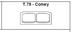
HEIGHT: 10.4 m
WIDTH: 24.1 m
TOTAL IMMERSED LENGTH: 710 m
DEPTH AT BOTTOM OF STRUCTURE: 17
ENVIRONMENTAL CONDITIONS: Sensitive historic and scenic area. River crossing. Required relocation of small boat anchorages
FABRICATION METHOD:
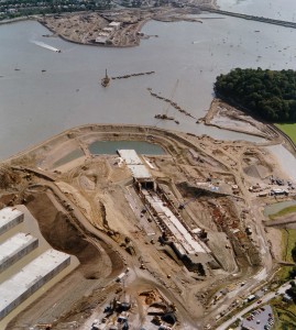
Elements were constructed together in a graving dock located next to the trench. Before casting, exterior waterproofing plates were placed on the bed. Each element was cast in segments, although continuous reinforcing was used. No cooling system was installed for the wall pours; but special coarse cement and pulverized fuel ash was used. Aggregates were cooled.
North Wales,
United Kingdom

Welsh Office
The principal contractor was a joint venture of Costain and Tarmac. Hollandsche Beton en Waterbouw were subcontractor for tunnel immersion and sand jetting.
Travers Morgan & Partners in association with Christiani & Nielsen A/S
118m
710m
17m
Project construction
1991-05-01
5
Two tubes; two lanes each
10.4m
24.1m
The first immersed tunnel in the U.K. Due to the traffic requirements in the U.K., the tunnel is approximately 2 m higher than usual. The tunnel is skewed to the river, with an angle of less than 45 degrees. Two elements curved in plan.
Elements were constructed together in a graving dock located next to the trench. Before casting, exterior waterproofing plates were placed on the bed. Each element was cast in segments, although continuous reinforcing was used. No cooling system was installed for the wall pours; but special coarse cement and pulverized fuel ash was used. Aggregates were cooled.
After all of the elements were completed, the dock was flooded and the dike was removed by dredging.
Before float-up of each element, two pontoons with lowering and mooring winches were floated over each element to be placed and hooked up to it. After deballasting, the element floated with the pontoons on top.
Before float-up of each element, two pontoons with lowering and mooring winches were floated over each element to be placed and hooked up to it. After deballasting, the element floated with the pontoons on top.
Sensitive historic and scenic area. River crossing. Required relocation of small boat anchorages
After winching the element to its location, it was placed by ballasting and lowering onto temporary footings.
Gina/Omega joint with six separate shear keys.
Continuous shear keys of concrete not provided at joint. Joint covered with stainless steel joint covers on inside of tunnel
Continuous shear keys of concrete not provided at joint. Joint covered with stainless steel joint covers on inside of tunnel
The underside and walls are waterproofed with steel plate protected by a paint system and cathodic protection. A concrete protected bituminous waterproofing membrane is provided on the roof.
Jetted-sand foundation. Delay in the start of sandjetting allowed sedimentation to occur under the tube. This was removed by airlifting.


