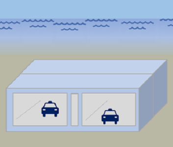
Sydney Harbour Tunnel
HEIGHT: 7.80 m
WIDTH: 29.4 m
TOTAL IMMERSED LENGTH: 960 m
DEPTH AT BOTTOM OF STRUCTURE: 25 m
ENVIRONMENTAL CONDITIONS: Very environmental sensitive area at scenic Sydney Harbour, with the Sydney Opera House almost in the alignment. These conditions led to the unique use of an adjacent bridge pylon for vent stack.
FABRICATION METHOD: The elements were built in two groups of four in a graving dock. The elements have continuous reinforcement, but were cast in sections.
Sydney,
Australia

N.S.W. Ministry of Public Works and Roads
Sydney Harbour Tunnel Group: Transfield Pty Ltd 50% Kumagai Gumi Co Ltd 50%
Main consultants: McDonald Wagner, Freeman Fox (HK) Rock tunnels and approaches: Mott, Hay & Anderson, Maunsell & Partners M&E: Parson Brinckerhoff, Gutterridge, Haskins and Davey Soil survey: Coffey and Partners
120m
960m
25m
Project construction
1992-04-30
8
Two tubes; two lanes each
7.80m
29.4m
Most northern element was laid against the ventilation building. A short stub section of tunnel built
into the ventilation building was provided with a sill beam to receive the first element. A cofferdam
was built over and around the end of the element; a tremie seal to the sandstone rock was made at
the front. To allow for differential settlement between element Nos 7 and 8, a special flexible joint
was attached to the end of element No 7. A permeable form was used to improve durability of
concrete for the elements.
The elements were built in two
groups of four in a graving
dock. The elements have
continuous reinforcement, but
were cast in sections.
groups of four in a graving
dock. The elements have
continuous reinforcement, but
were cast in sections.
Elements were cast in Port Kembla, 100 km away. Extensive
model studies were undertaken to assure feasibility of tow. A
freeboard of 0.5 m was used during tow. At the outfitting pier in
Sydney, further ballast and placing equipment was installed,
bringing elements to 10 cm of freeboard.
model studies were undertaken to assure feasibility of tow. A
freeboard of 0.5 m was used during tow. At the outfitting pier in
Sydney, further ballast and placing equipment was installed,
bringing elements to 10 cm of freeboard.
Very environmental sensitive area at scenic Sydney Harbour, with the Sydney Opera House almost
in the alignment. These conditions led to the unique use of an adjacent bridge pylon for vent stack.
in the alignment. These conditions led to the unique use of an adjacent bridge pylon for vent stack.
Transverse pontoons.
Gina and Omega type of joint.
A special prefabricated
settlement joint was provided
on element No 7, which was
founded on sand. Element No
8 was connected into a
sandstone wall and a tunnel
was mined to it.
A special prefabricated
settlement joint was provided
on element No 7, which was
founded on sand. Element No
8 was connected into a
sandstone wall and a tunnel
was mined to it.
A PVC membrane was used on the bottom. The sides and top were covered with an epoxy resin
coating. Low heat of hydration with good impermeability to chloride ion penetration was achieved
using a high replacement blend of Type A cement and ground granulated blast furnace slag.
Suphate resistance was also good.
coating. Low heat of hydration with good impermeability to chloride ion penetration was achieved
using a high replacement blend of Type A cement and ground granulated blast furnace slag.
Suphate resistance was also good.
Sand-flow method utilizing pipes installed in the walls from the roof slab to the base slab. Element
No 8 was supported on a foundation of cement-based grout. The other elements were founded on
sand.
No 8 was supported on a foundation of cement-based grout. The other elements were founded on
sand.
A 2 m cover of rock fill with rock armour flanks was provided. The rock fill was designed to absorb
the impact of a falling anchor; the rock armour was designed to deflect an anchor dragged across
the tunnel.
the impact of a falling anchor; the rock armour was designed to deflect an anchor dragged across
the tunnel.

