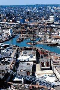
Fort Point Channel Tunnel
HEIGHT: 7.9 m
WIDTH: 21.34 m minimum 47.25 m maximum
TOTAL IMMERSED LENGTH: Two separate tunnels
approximately 330 m long
DEPTH AT BOTTOM OF STRUCTURE: 17.7 m
ENVIRONMENTAL CONDITIONS:
Crosses historic channel no longer used for navigation. Mild currents produced by tidal
action and storm water runoffs. Tide range quite large: 4 m. Both shores heavily
congested with industrial activities. Existing bridges restrict access to site in width and
height.
FABRICATION METHOD: The six elements will be
constructed in the east approach excavation in three
cycles of two elements each.
Boston, Massachusetts,
United States

Massachusetts Highway Department
Immersed tunnel contract not out for tender as yet.
Gannett Fleming, Inc. ACER Engineers & Consultants, Inc.
99 m minimum 127 m maximum
Two separate tunnels approximately 330 m long
17.7m
Project construction
6
East Bd. Tunnel: 3 Tubes: 5 Lanes + Transitions West Bd. Tunnel: 2 Tubes: 4 Lanes + Transitions
7.9m
21.34 m minimum 47.25 m maximum
Two parallel immersed tunnels with only 1.2 m separation between them. The tunnels
are both to cross over two existing operating subway tunnels. The space in between
the I-90 Tunnels and the Red Line Subway tunnels will be only 1.5 meters. The
elements will be placed in alternating sequence in pairs starting on the west end and
ending on the east end. The west end of both tunnels will be provided with large, 7.3 m
tall “snorkles” which will form the foundations for the vent building which will straddle the
tunnels.
The six elements will be
constructed in the east approach excavation in three
cycles of two elements each.
constructed in the east approach excavation in three
cycles of two elements each.
Installation of
temporary cofferdam walls
will be made on top of last
two elements to permit final
dewatering for connection
of cut-and-cover tunnels on
east end.
temporary cofferdam walls
will be made on top of last
two elements to permit final
dewatering for connection
of cut-and-cover tunnels on
east end.
Crosses historic channel no longer used for navigation. Mild currents produced by tidal
action and storm water runoffs. Tide range quite large: 4 m. Both shores heavily
congested with industrial activities. Existing bridges restrict access to site in width and
height.
action and storm water runoffs. Tide range quite large: 4 m. Both shores heavily
congested with industrial activities. Existing bridges restrict access to site in width and
height.
Conventional pontoon method of placement is precluded due to insufficient water depth.
Placement will most likely be done using a system of cables and winches operated from
the shore areas surrounding the tunnels on three sides. Temporary lowering towers
constructed out in the channels may be also used for lowering and positioning each
element.
Placement will most likely be done using a system of cables and winches operated from
the shore areas surrounding the tunnels on three sides. Temporary lowering towers
constructed out in the channels may be also used for lowering and positioning each
element.
Gina and
Omega gaskets except on
east end where cut-andcover
connection will be
made to element in the dry.
Omega gaskets except on
east end where cut-andcover
connection will be
made to element in the dry.
Spray membrane using acrylic or polyurethane resins on sides and top. Ribbed
polyethylene sheet on bottom (current design).
polyethylene sheet on bottom (current design).
Options will be provided in the contract for either using a screeded bed or a pumped
sand foundation.
sand foundation.
There is no vertical room available for cover except for a concrete protective layer on
top and locking fill on the sides of each tunnel.
top and locking fill on the sides of each tunnel.

