Atsumi Karyoku Cooling Water Tunnel
HEIGHT: 4.0 m
WIDTH: 8.4 m
TOTAL IMMERSED LENGTH: 36.5 m
DEPTH AT BOTTOM OF STRUCTURE: 18.0 m
FABRICATION AND OUTFITTING:
The horizontal elements having lengths of 18.7 m, 30.5
m and 30.4 m respectively were sunk by pneumatic caisson
method. The immersed element was fabricated of
reinforced concrete in a temporary drydock over two of
the three horizontal caissons. The lower half of the water
intake caissons were fabricated off site 36 km away at
the Isle Ohmineto dockyard. The upper part was finished
at the site. The immersed tube was fired with 4 hydraulic
jacks, alignment towers and access manholes.
ENVIRONMENTAL CONDITIONS: Open seashore.
Atsumi Peninsula,
Japan

Chubu Electric Power Company, Inc
Hazama Corporation
36.5m
36.5m
18m
Project construction
1970-04-30
1
Two tubes
4m
8.4m
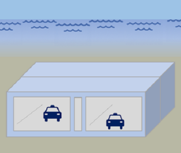
Tunnel consisting of three caissons and one immersed element. The immersed element
inclines with the steep gradient of 1:3.4 down to the water intake caisson. The total
length of the intake is 119.4 m
inclines with the steep gradient of 1:3.4 down to the water intake caisson. The total
length of the intake is 119.4 m
The horizontal elements having lengths of 18.7 m, 30.5
m and 30.4 m respectively were sunk by pneumatic caisson
method. The immersed element was fabricated of
reinforced concrete in a temporary drydock over two of
the three horizontal caissons. The lower half of the water
intake caissons were fabricated off site 36 km away at
the Isle Ohmineto dockyard. The upper part was finished
at the site. The immersed tube was fired with 4 hydraulic
jacks, alignment towers and access manholes.
see above
Open seashore.
After floating test in the drydock, the immersed element was moved into position and
lowered using two cranes at the outboard end and one crane at the inboard end.
lowered using two cranes at the outboard end and one crane at the inboard end.
Rubber gasketted flexible joint from immersed tube to
intake caisson to provide for difference in natural seismic
frequencies. The caisson end was joined rigidly to the land:
structures.
intake caisson to provide for difference in natural seismic
frequencies. The caisson end was joined rigidly to the land:
structures.
Waterproofing was not required for water intake.
Screeded bedding was used for the 1:3.4 gradient after which the voids were grouted.
1.5 m of sand backfill at the top of the tunnel with stone along the sides to protect
against tidal currents, wave action, and earthquake action.
against tidal currents, wave action, and earthquake action.


