Oakland-Alameda (Posey) Tunnel
TOTAL IMMERSED LENGTH: 742 m
DEPTH AT BOTTOM OF STRUCTURE: 25.5 m
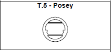
HEIGHT: 11.3 m (dia)
WIDTH: (circular)
FABRICATION METHOD: In drydock with five elements per cycle, chuted concrete,
steel forms.
SITE CONDITIONS: river
DEPTH AT BOTTOM OF STRUCTURE: 25.5 m
HEIGHT: 11.3 m (dia)
WIDTH: (circular)
FABRICATION METHOD: In drydock with five elements per cycle, chuted concrete,
steel forms.
SITE CONDITIONS: river
between Oakland and Alameda, California, U.S.A.,
United States
(between Oakland and Alameda)

Alameda County bond holders
California Bridge and Tunnel Co
George A Posey Chief Engineer; W.H. Burr, Ole Singstad and Charles Derleth, Jr.
61.9m
742m
25.5m
Project construction
1928-04-01
12
One tube; two lanes; one each way
11.3m (dia)
circular
Circular concrete section (without steel shell) was cast in a drydock. Waterproofed with
external membrane protected with timber lagging. Invert waterproofing was laid on
timber lagging and ended by metal flashing at end brackets. Roadway slab and ceiling
tierods were used for structural members. Placement and foundation methods were
very unusual. 122 m at south end were founded on pile-supported tremie concrete
cradle. Tunnel ends (vent buildings) are National Historic structures. This tunnel is a
significant early example of the Art-Deco Style by Architect Henry H. Meyer.
In drydock with five elements per cycle, chuted concrete,
steel forms.
steel forms.
At time of fabrication
Ballasting involved placing dry sand on the floor slab before and after the element was
positioned over the trench. The lower duct was filled with sea water and an additional
load of sand was placed. The final load adjustment was made by wetting the sand on
the roadway slab. For the first five joints, sand jacks mounted on pile supported piers
were used to land the elements. This method was simplified by using timber grillages
lowered to bear on piles driven 15 cm high, to allow for settlement. This grillage was
intended to crush under settlement. If the element was not to suitable grade, some of
the sand bed had to be removed - a very difficult and time-consuming operation. The
elements were supported by a derrick barge at one end and leads from a pile driver at
the other. Lateral movements were controlled by lines from winches mounted on
dolphins. Immediately after being set in position, more water ballast was added. The
exterior sand bed was placed by pumping a sand slurry under the element as directed
by divers. On completion of the sand bed, the element was filled with water. The tremie
joint was made and completed from inside later. Before dewatering or removing ballast,
at least 3.4 m of backfill had to be placed to overcome buoyancy (the stability of the
tunnel depends on this cover being maintained throughout its life!).
Tremie concrete joints.
Invert waterproofing was laid on timber lagging and ended by metal flashing at end brackets.
See PLACEMENT METHOD
Reinforced

