Elbe Tunnel
HEIGHT: 8.4 m
WIDTH: 41.7 m
TOTAL IMMERSED LENGTH: 1,056 m
DEPTH AT BOTTOM OF STRUCTURE: 29 m
ENVIRONMENTAL CONDITIONS: River currents of 1.3 m/s (flood)
FABRICATION METHOD: All eight elements were constructed at the same time in a casting basin. 190,000 m³ were first removed by dredging. Then, after closing the end with a 250 x 11 m cofferdam, 380,000 m³ were excavated in the dry.
Hamburg,
Germany

Freie und Hansestadt Hamburg
Arbeitsgemeinshaft “E3 Elbtunnel” consisting of Dyckerhoff & Widmann A.G., Hochtief A.G., Ways & Freytag A.G., Christiani & Nielsen Ingenieurbau A.G. (Hamburg)
Joint Venture “E3 Elbtunnel”, see below, except for submerged tunnel: Christiani & Nielsen, Copenhagen
132m
1,056m
29m
Project construction
1975-04-30
8
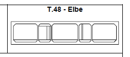
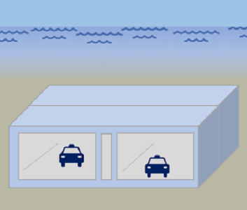
Three tubes; two lanes plus lane for slow traffic each
8.4m
41.7m
Very wide tunnel, with six lanes providing reverse traffic flow in middle two lanes.
Prestressed concrete design was investigated for both transverse and longitudinal
loads; conclusion was that it was not economical. Joints were provided at 27 m intervals
for both temperature and settlement effects. Initially it was decided that these
intermediate joints were unnecessary; however, because of uncertainty in predicting
settlements, they were eventually included. Special exterior Omega steel plates were
used at these joints. Joint was held together by prestress bars until tunnel element was
in place on jetted foundation, bars were then cut to allow flexibility. The river channel
was switched from one side of the river to the other during construction
All eight elements were constructed at the same time in a
casting basin. 190,000 m³ were first removed by dredging.
Then, after closing the end with a 250 x 11 m cofferdam,
380,000 m³ were excavated in the dry.
casting basin. 190,000 m³ were first removed by dredging.
Then, after closing the end with a 250 x 11 m cofferdam,
380,000 m³ were excavated in the dry.
River currents of 1.3 m/s (flood)
Deck-mounted square pontoons with control and alignment towers. Each tunnel
element had 12 ballast tanks with a total capacity of about 5,000 m³. Buoyancy
depended almost entirely on the weight of the concrete. The density, as well as the
concrete dimensions, were continuously controlled and the findings treated statistically,
in order to maintain the total weight within 0.5% of theoretical. Because of the river
currents, piled anchorages to pull against were established in the river bottom. Between
seven and nine 1,200-Hp tugs were used to tow and position elements.
Gina gasket joint with rubber Omega interior gasket.
Joints allows for longitudinal expansion and contraction.
Joints allows for longitudinal expansion and contraction.
Steel membrane on bottom and side. Bituminous membrane on top protection with 15
cm of concrete. Waterstops and steel Omega (re-entrant) joints at intermediate joints
(corners formed, not mitered)
cm of concrete. Waterstops and steel Omega (re-entrant) joints at intermediate joints
(corners formed, not mitered)
Sandjetting. Element No 8 ran
into a problem with excess mud deposits. This material
was removed before placing the sand.
into a problem with excess mud deposits. This material
was removed before placing the sand.
Reinforced


